
The Ives Kromskop
written by Paul Wing, USA. First published in Stereo World 1988 (15/1), used with kind permission of the National Stereoscopic Association.
Unless otherwise stated, all pictures were taken from the Stereo World article.
One of the most remarkable stereoscopes ever produced commercially was the Ives Kromskop (Patent #531,040, Dec 18, 1894). In it, three stereoscopic glass positives made from negatives exposed through red, green, and blue filters are optically superimposed to give a full color image of remarkable quality. It was more than ten years prior to the introduction of relatively crude full color plates such as the Autochrome.
This viewer and a complementary one-shot color camera were inspired by Frederic Eugene Ives (1856–1937), a pioneer in the field of halftone printing where he held many important patents. The reproduction of nature in full color was his other absorbing interest. It occupied so much of his time that he founded a company at 1324 Chestnut Street in Philadelphia that remained in business over forty years even though mass acceptance of any of his ideas never came to pass. A New York showroom was also established at 18W. 33rd St.
Early attempts

In 1861, James Maxwell, the British Physicist, showed that by projecting superimposed red, green, and blue images, a full color image could be produced. Lack of color sensitive (panchromatic) film in those days was a serious drawback, and some thirty years passed before the emulsions existed which Ives used in making his color separations.
Ives’ first color patent #672,573 (July22,1890) described the basic three color (additive)process and the use of three positive images in a special triple lantern to produce a full color image on the screen (Fig. 1). He also covered the use of negatives in the production of printed color images using the halftone process. The printing colors then become cyan, magenta and yellow, the complementary (subtractive) colors for red, green, and blue. Announcement of his achievement led to an invitation to England in 1892 which lasted for two full years as he “captured crowded audiences at a series of lectures:’
He returned to America in April 1894 and set about putting his ideas into commercial form. This led to the invention of a viewing device first known as the Photochromscope. He was back in England little more than a year later both to promote his halftone process and to introduce the perfected viewer now named the Kromskop. In 1896, the British Kromskop Syndicate was formed to exploit this invention, but it was never successful and the project was terminated in 1898 when Ives returned to Philadelphia. His long sojourn and great promotional activity in England and on the Continent help to explain the relative abundance of these rare viewers on the overseas market.

The real challenge was to find a practical way for optically combining six images to produce a color stereo image. The first images were made on a single glass plate, side by side to fit conveniently in the triple lantern projector. The same three images in the original Ives Photochromscope viewer, although only monocular, required seven reflectors, six lenses, plus the three color screens. The stereo Kromskop finally reached the market with only two tinted transparent mirrors, an external reflector for distribution of illumination, two additional color filters, and the viewing lenses.
The problem had been tackled by other inventors without success. In Fig. 2 a simple arrangement dating back at least twenty years is shown, using a mirror C and two plain glass reflectors A and 8. The three separations are placed ahead of the appropriate color filters and the distance from the viewing lens is constant. There are two basic problems. The optical path is too long, making the picture very small. Also, the glass mirrors, which both transmit and reflect, create annoying double images.
Final form
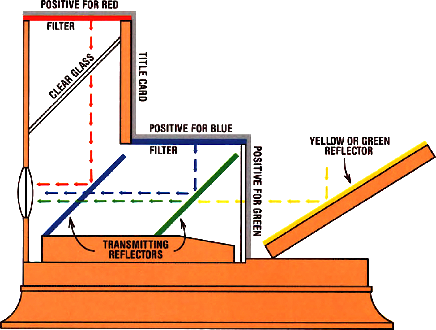
Ives’ ingenious solution is diagramed in Fig. 3. The original mirror C is eliminated to shorten the optical path. A green transmitting reflector is used for the blue image, and blue for the red image. The green reflector also serves as the color filter for that image. When the red or blue images are reflected from these tinted mirrors, the annoying secondary image that normally bounces off the back side of the glass is absorbed by the complementary color in the glass.
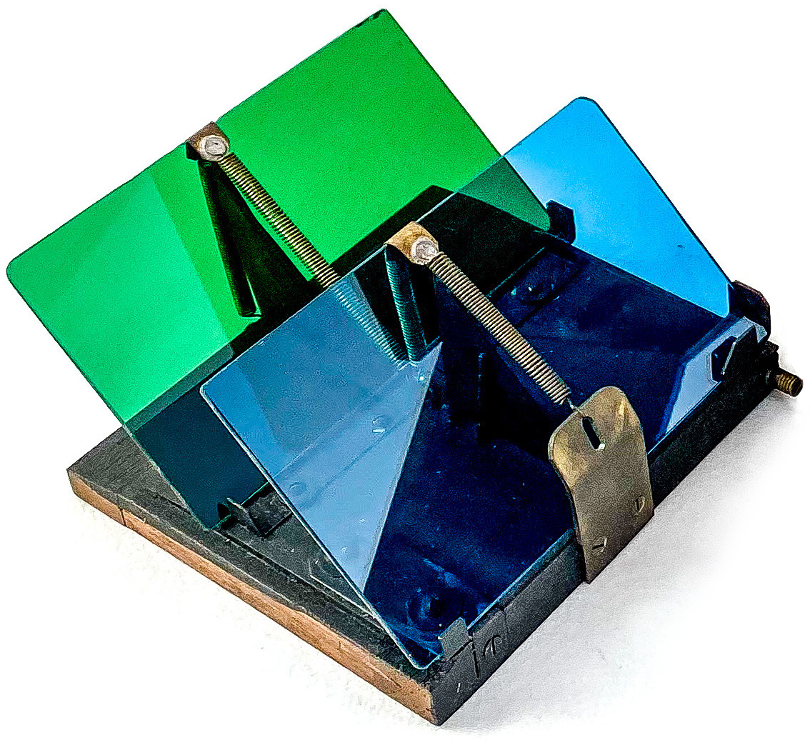
Initial alignment of the viewer is accomplished by the angle and squareness of the two transmitting reflectors shown in Fig. 4. The glasses are spring loaded against rotatable triangular stops to allow a small change in inclination. Through this adjustment, the red or blue images can be raised or lowered independently with respect to the green. The base support for the mirrors can be rotated for initial horizontal alignment. These are normally factory adjustments, but they sometimes have been tampered with and it is not easy to bring back proper alignment. In the early versions, these adjustments were crude. Later versions have threaded verniers that are a great help if things are truly out of line.
The block on which the reflectors are mounted fits slidably into the instrument, coming to rest against a small eccentric wheel. Turning a knob on the outside of the viewer moves the assembly back and forth a small amount. This simultaneously raises and lowers the red and blue images to line them up with the green. In a later design, a threaded screw at the right front of the viewer provides the same function in a more positive manner.
Commercial product
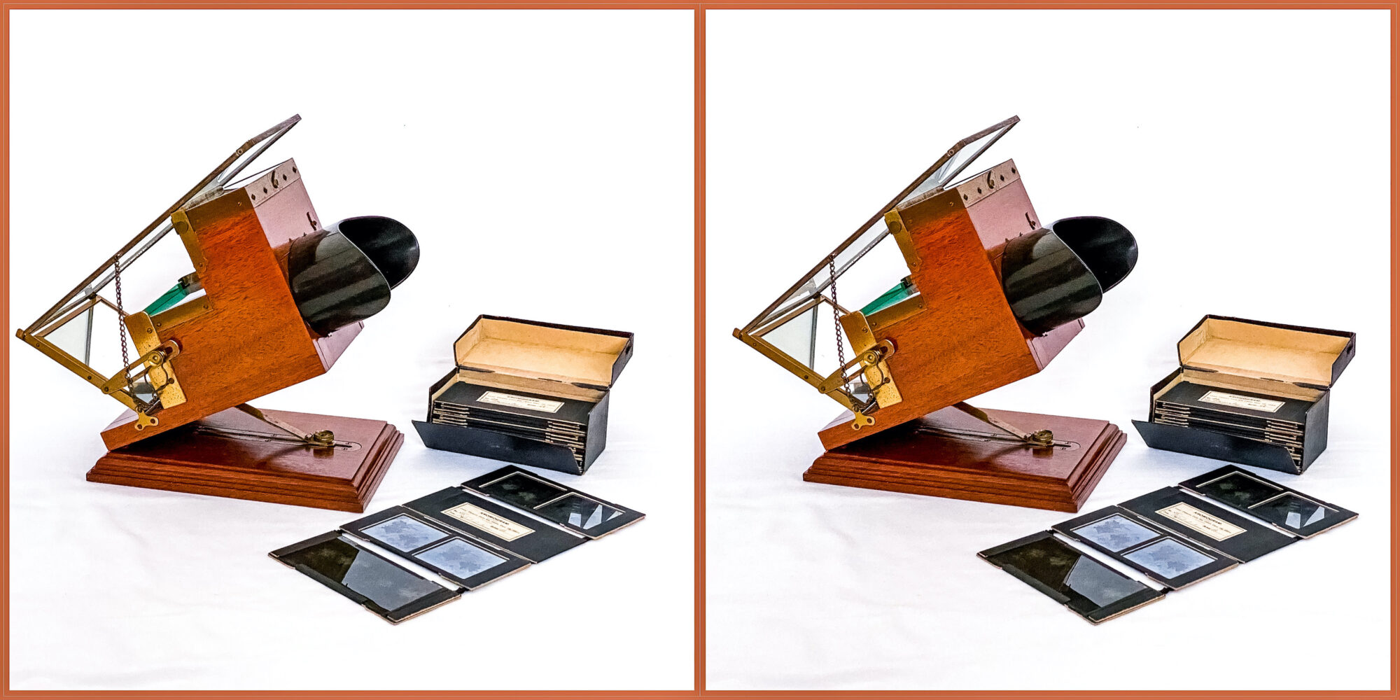
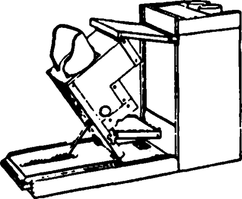
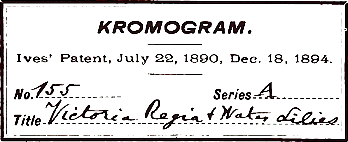
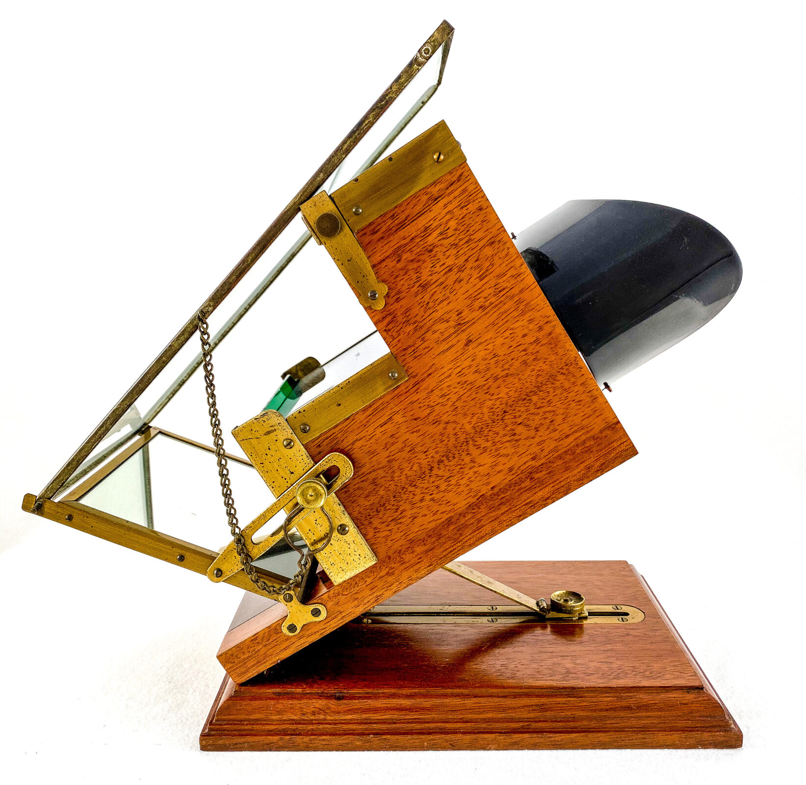
The commercial product, (Patent #531,040, Dec. 18, 1894) is illustrated in Fig. 5. It is a precision device of polished mahogany and brass most likely made in England with final assembly and calibration in Philadelphia. When properly aligned and illuminated, the results are quite spectacular. Superimposing six 2″ by 2″ quality images virtually eliminates grain. The three pairs are precision mounted in masks and held loosely together by silk tapes and are fan-folded for storage (Fig. 6). The positive green image slips into a slot at the rear and is non-adjustable. The blue image lies horizontally on the first step in two-point contact with a factory aligned brass plate. Only a very small horizontal adjustment is possible. The red image mounts similarly at the top, with the addition of a vernier screw at the left for precise horizontal adjustment only. The spacer card between the red and blue images bears the title.

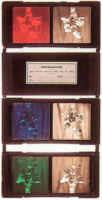
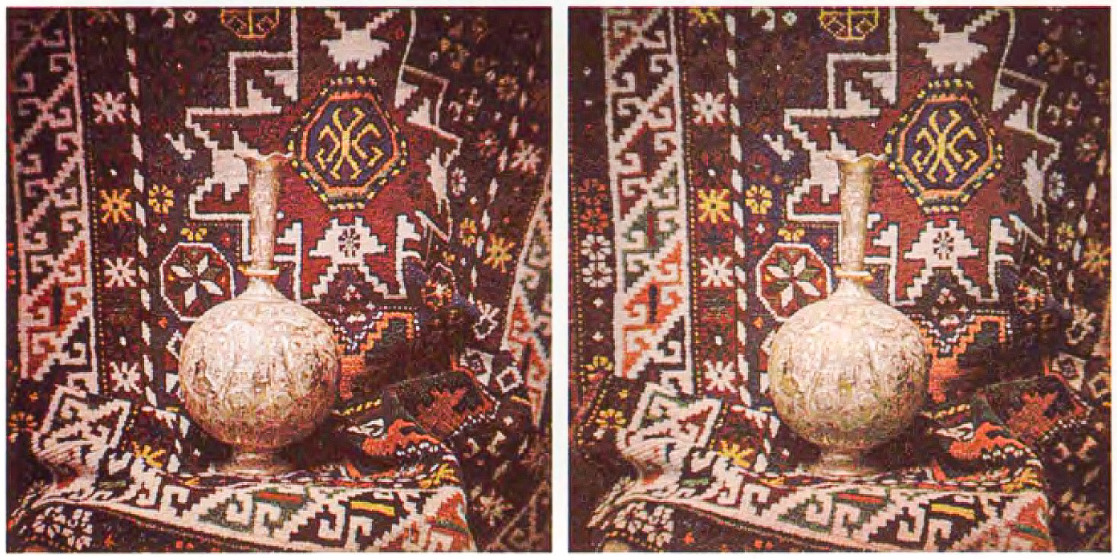
A complete Kromogram unfolded on a light box with the left images filtered to show the color which would be provided and combined by a Kromskop viewer. Except for the green, the images are inverted and reversed for viewing in the transmitting reflectors shown in figure 4. Kromogram windows are exactly 2″ wide with a three-sixteenth inch septum and only 55mm center to center. The mounts are 5.25″ wide.
Notes on use
In use, the viewer is always tipped up to improve illumination, to ensure that the red and blue images lie against the stops, and to make the vernier on the reflectors operate properly.
Proper illumination is most important. A daylight diffuser (Fig. 7) was standard equipment, but it is generally missing. It was of opal glass, mahogany edged, and rested on the two pins at the back of the reflector. A chain permits it to be swung to the rear for changing slides. Ground glass is not a suitable substitute. Normal illumination was by skylight. At night the “Kromskop Night Illuminator” was available for $12 (Fig.8). Two Welsbach gas burners were used and the exterior housing was of polished mahogany and brass.

The reflector at the rear of the viewer sends light through the “green” image. In some instruments, the mirror is tinted green, but it can be a more neutral color such as yellow since the true spectral filter is a transparent mirror inside the viewer. By sliding out the block containing the mirrors, the viewer becomes an ordinary stereoscope for viewing specially mounted glass stereograms or for looking at the “green” image as a black and white positive.
The design just described introduces a small error in registration due to the fact that the green image passes through two slanted transparent mirrors which slightly compress the image vertically. The blue image passes through just one. In compensation, a plain glass (double the thickness of the mirrors) is placed at the same angle just below the “red” image (Fig. 3). This brings the important red and green images into correct register, leaving a small error in the blue which in practice is not noticeable.
Taking pictures
The pictures were generally taken on a single glass plate. For still lifes, a multiple back was sold to use vertically split 5″ by 7″ plates (Fig. 9). A stereo version of this back was also produced using the full plate. Positives made by contact printing were reversed right to left unless a reversing mirror of prism was fitted in the lenses. Glass plates, mounting frames and other supplies plus a mounting service were available. The positives are ready for cutting and mounting directly on the Kromogram frames, but nothing is said about the requirement for great accuracy. Register is on the same order as that used today for lap dissolve pairs.

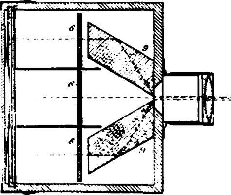
For instantaneous photographs an ingenious “one shot” camera was produced. In the diagram (Fig. 10) the prisms F and G are placed so that their inner front edges partially cover a rectangular aperture in the lens system. The double internal reflection leaves the two images unreversed, and the greater refractive index of the glass compensates for the longer light path. The camera required exposures on the order of five to ten seconds in bright sunlight. It was priced at $75 with the stereo version projected at something less than double that price. In making single views for the lantern Kromskop, the camera was used in the horizontal position. The later stereo version pared the cameras vertically, allowing a “normal” lens separation.
Available picture series
The Kromskop came with eight Kromograms for $50. A large selection of Kromograms was available, the “A” Series priced at $1 ($10 per dozen) and the “B” Series at $1.50 ($15 per dozen). One 12-page price list covers almost 400 subjects.
While perhaps not a major factor in the failure to achieve commercial success, the pictures as a whole are disappointing. Exposure, general print quality, and color rendition are excellent, but the photography was by people with little or no understanding of good stereo composition.
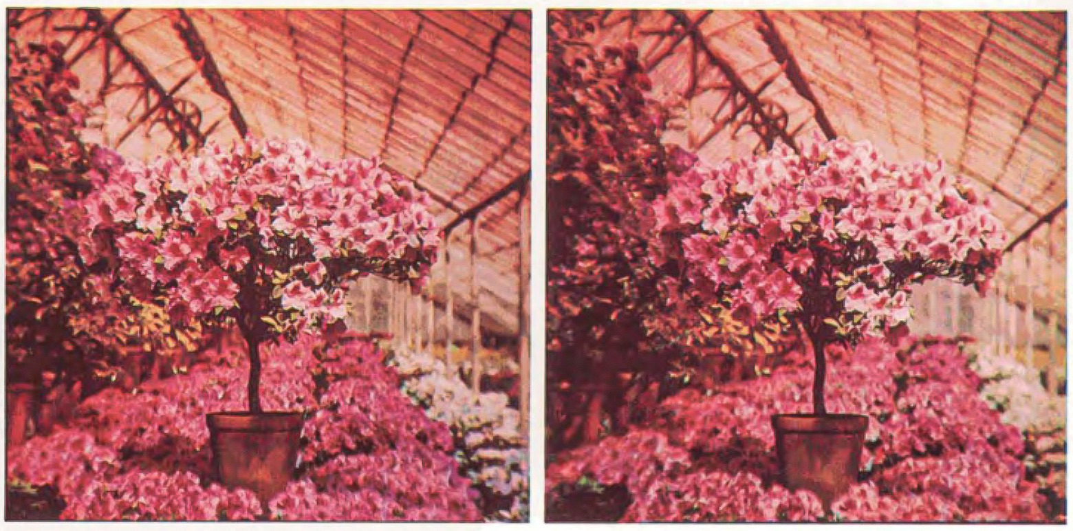
Outdoor scenes were particularly poor. A group of people including Ives visited Paris in 1897–98 proceeding on to Switzerland, and about three dozen views were published as a result. Scarcely one has a foreground object within 100 feet of the camera, and the need for near perfect registration makes them generally disappointing in the viewer. Even more remarkable was the promotion of upwards of 100stereo pictures of paintings from the National Gallery in London! Still lifes were casually set up with little regard for esthetics. Some thought was given to choosing subjects that demonstrated nuances in color. Some of the flower arrangements are very good, primarily because of the excellent color reproduction.
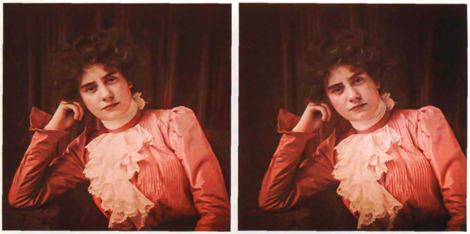
A special set of medical views was produced in the hope that the medical profession would recognize the great benefits of full color 3‑D. Views were offered from Paris, London, Philadelphia, Niagara Falls and Washington DC. A series of still life subjects and a small number of portraits were an important part of the listings. A portrait of Mrs. McKinley in the White House Conservatory was taken at the same time as the widely distributed Underwood and Underwood view card.
Conclusion
In summary – if you own a Kromskop and have some fine examples to show, treat them with care and be chary about acquiring additional ones which may be mediocre examples from the published lists or even poorer amateur efforts.
No information is available on the number of views produced. Design variations suggest that several small production runs were made, with sales of the last units spread out over a number of years.
Proper illumination and register of the views was a serious drawback. The expense and relatively poor quality of the commercial views must have been a factor. Making Kromograms demanded more skill than the average amateur could give to it. It all added up to failure in spite of the enthusiasm of the professional critics.

At least one competitive system appeared briefly around 1900.It was known as the “Kromaz”. A single lens camera using mirrors made two exposures, and the resulting four images, one red, two green and one blue were optically combined in a viewer.
In the meantime, other inventors, notably the Lumière brothers, were working towards direct color transparencies based on the additive color process. In 1907they began marketing Autochrome plates (including stereo sizes), the first commercially successful color process. It wasn’t until 1935that the superior subtractive color process to be known as Kodachrome virtually put an end to efforts using the familiar red, green, and blue filters.
The Kromskop is seldom mentioned today. Relatively few people have had the opportunity to see properly illuminated views in a Kromskop. These reproductions are the first ever done in 3‑D. They are a reminder of the tremendous achievement of this great inventor.
The author wishes to thank George Eastman House and the International Museum of Photography in Rochester, NY for their help with images and information in this article.
Paul Wing (Hingham, Massachusetts, USA)
Paul Wing was born in Sandwich, Massachusetts on March 9, 1913. Paul was first intrigued with stereocards in the early 1920s and by the time he finished high school during the Great Depression he was making “cha cha,” stereo photographs using side-step with a [2D] Kodak Brownie camera. In the 1940s, Paul met Dr. Philip Batchelder, a stereo collector and a member of the American Branch of the Stereoscopic Society of Great Britain. “It opened a New World,” Paul wrote in the foreword to his book on stereoscopes.
The importance of Paul Wing in contemporary stereography cannot be overstated. Paul was a veteran of more than a half century of stereoscopy and was one of only four Lifetime Members in the Stereoscopic Society of America (SSA). Member number 385 in the SSA, Paul was an internationally recognized master stereographer and the author of “Stereoscopes: The First One Hundred Years,” (Transition Publishing: 1996), the definitive history on the subject and one which will undoubtedly remain so for a long time to come.
He passed away on March 7, 2002 two days before his 89th birthday.
Full text: 3D Legends
Notes by Pascal Martiné: This article was first published 35 years ago. It is thanks to David Starkman’s presentation for the Virtual Stereoscopic Community that this article is now available to a wider audience. Transferring a print layout to a digital medium requires to pay attention to multiple aspects. That’s why I have allowed myself to re-arrange the pictures within the text and to optimize the graphics. Therefore, I replaced some pictures with newly taken digital photos of my own Kromskop, optimized all graphics and gently sharpened the pictures of Paul Wing’s Kromograms (without changing the color appearance). Finally, because it has become common practice with blog posts, I added subheadings.